- Published on
File System Performance

The one major difference that exist in file systems is that when a machine turns off, processes cease to exist, ram gets unallocated but files remain persistent.
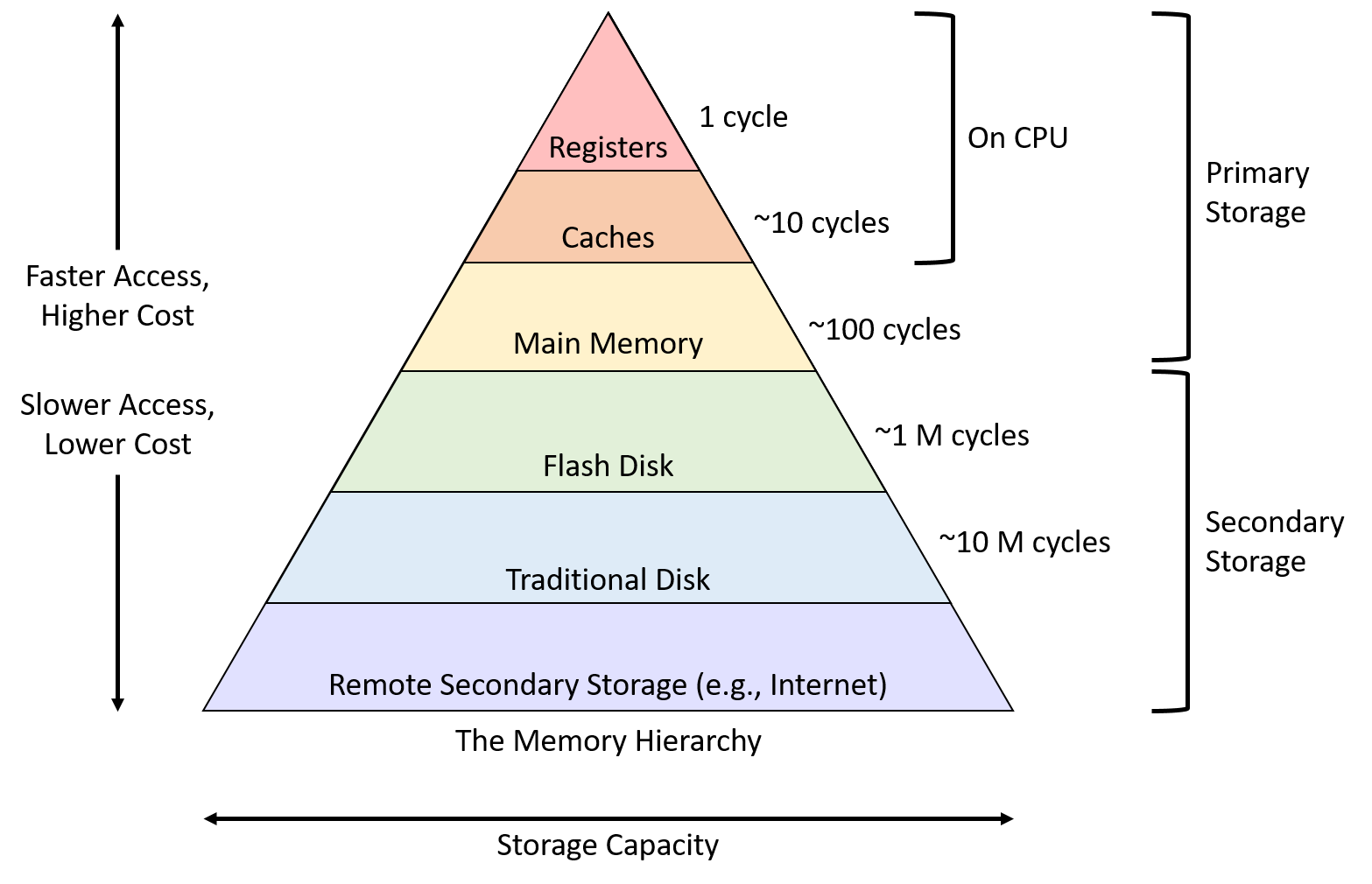
Storage Hierarchy
- File systems are a hybrid data structure, part of the mapping is in the RAM, and the other half is in the physical device in long term storage
- One of the key performance concerns has to do with what is stored in the persistent storage and what is stored in the RAM
Metrics for I/O
- For I/O bound performance, the CPU performance does not matter, we care about:
- Utilization (%): Percentage of IO capacity in use (how busy is your system)
- Throughput (1/time): Rate of request completion
- Generally, the better the utilization, the higher the throughput. However, the throughput matters for the user, and the administrators care about the utilization
- Latency (t): The difference in time between the request and the response
Usually, there has to be a balance between latency and throughput where improving one can come at the cost of another.
Locality of Reference
- Spatial Locality: if an application accesses a part of a file somewhere, it might access a part of another file that is close by
accessing a[i] might induce accessing a[i-1]
- Temporal Locality: If a application accesses a part of a file somewhere at a specific time, it might access that same file at another time in the future
- accessing
a[i] at time tmight induce accessinga[i] at time t+1
- accessing
File System Levels
Block-Level Caching
How It Works:
- When a program writes data, the data isn't immediately written to the disk. Instead, it's stored in a cache in the kernel. This approach improves performance because writing to a cache in memory is much faster than writing to a disk.
Visualization:
- Suppose you have a series of blocks on the disk:
[][][][][][][][][][][][][] - When
write(block2, 10)is called, the data (10) is written to the cache, not directly to the block:Block Level: [][10][][][][][][][][][][][][] Cache: [10]
- Suppose you have a series of blocks on the disk:
Issue of Data Loss:
- The major risk here is data loss in the event of a system crash or power failure. Since the data is only in the cache and not yet written to the disk, any unsaved data in the cache could be lost.
Synchronization System Calls
To mitigate this risk, there are several system calls designed to synchronize the cache with the actual storage on disk:
sync():- Writes all outstanding changes in the kernel's cache to disk. This includes data from all processes and system buffers.
- Usage: It's a broad sweep and ensures data integrity but can be expensive in terms of system resources because it forces all cached writes to disk.
fsync():- Similar to
sync(), but it's limited to a specific file. - Usage: It's used to flush all changes associated with a file referenced by a file descriptor.
- Performance: Generally less expensive than
sync()as it targets a single file, not the entire cache.
- Similar to
fdatasync():- Similar to
fsync(), but it only affects the file's data portions, not its metadata (like last access or modification times). - Usage: This can be used for scenarios where you're only interested in ensuring the file's data is safe, not its metadata.
- Performance: Can be faster than
fsync()in certain situations, as it does less work.
- Similar to
Scheduling the Buffer Cache
In a computing system, the kernel's buffer cache is a critical component for improving I/O performance. Effective management of this cache involves smart scheduling strategies that maximize its use and ensure smooth access to data.
Ensuring Effective Use of Cache
The primary goal of the kernel in managing the buffer cache is to ensure that the cache is utilized efficiently, which involves:
- Reducing I/O Overhead: Minimizing the number of read/write operations to the disk.
- Optimizing Access Patterns: Aligning disk access with the application's data access patterns.
- Balancing Cache Usage: Maintaining a balance between holding on to frequently accessed data and making room for new data.
Speculation Strategies
Speculative techniques in caching are about predicting future actions and optimizing performance based on those predictions.
Speculation for Reads
Prefetching:
- The idea is to anticipate what blocks of data an application might read next and load them into the cache in advance.
- For instance, if a program is reading through a file sequentially, the kernel can prefetch subsequent blocks of that file.
Batching:
- When a read request for a block is received, the kernel might fetch adjacent blocks as well, assuming that these blocks might be needed soon.
- This is especially effective for workloads with sequential access patterns.
Speculation for Writes
Prefetching for Writes:
- Prefetching doesn't apply to writes as it does for reads. Write operations are usually initiated by the user and can't be anticipated in the same way.
Dallying:
- Instead of writing data to disk immediately, the kernel can delay (dally) these operations.
- This allows for the aggregation of multiple small write operations into a single larger one, thereby reducing the number of write operations to the disk.
Batching:
- Similar to reads, the kernel can batch multiple write operations together.
- When the user requests a write, the kernel can combine this with other pending write operations to optimize the disk I/O.
Advantages and Challenges
- Performance Improvement: These speculative techniques can significantly enhance overall system performance by reducing disk I/O overhead.
- Complexity in Prediction: The challenge lies in accurately predicting future read/write operations. Incorrect predictions can lead to unnecessary disk I/O and reduced performance.
- Resource Management: Managing the buffer cache also involves making decisions about which data to keep and which to evict, which can affect both performance and data integrity.
- Balancing Act: The kernel must balance between holding data long enough to be useful and writing data back to disk promptly to ensure data integrity.
Understanding How Disks Work
Disks, specifically Hard Disk Drives (HDDs), are a fundamental part of computer storage systems. They are known for offering a high capacity of storage at a relatively low cost per byte. Here's a breakdown of how they operate:
Physical Structure:
- Disks are composed of magnetic platters, each of which is divided into circular tracks.
- These tracks are further divided into sectors, which are the smallest units that can be read or written on a disk.
- A cylinder comprises the set of all tracks that are at the same position on each platter and can be accessed without repositioning the disk heads.
RPM (Revolutions Per Minute):
- A typical disk speed is 7200 RPM, which means the disk completes 7200 revolutions in a minute. This equates to 120 revolutions per second (120 Hz).
Reading and Writing Data:
- Data is read and written by floating a read/write head very close to the surface of the spinning disk. This head moves across the platters to access different tracks and is positioned over the correct sector to read or write data.
- The read/write head doesn't physically touch the platter; rather, it hovers just above it.
Accessing Data
- Send Command: The request is sent to the disk controller, a hardware component that controls the disk.
- Seek Time: The disk head moves to the correct track. This is called seeking, and it takes a certain amount of time (e.g., around 10ms).
- Rotational Latency: Once the head is over the correct track, it waits for the disk to rotate the correct sector under the head. This time is typically about 4ms.
- Transfer Time: This is the time it takes for the sector to pass under the read head, allowing the data to be read.
- Data Transfer to Controller Cache: The read data is first transferred to the controller's cache.
- Transfer to RAM: Finally, the data is transferred from the controller cache to the system's main memory (RAM).
Disk Scheduling
Simple Model (Only Seek Time with 1 Platter)
- Description: In this model, only the seek time (the time taken for the disk head to move to the desired track) is considered.
- Example: If the disk head is at position 'h' and needs to move to 'i', the seek time is proportional to the distance |i-h|.
- Goal: Maximize throughput (amount of data transferred per unit time) and prevent starvation (a situation where a request is never serviced).
First Come First Serve (FCFS)
- Description: Requests are serviced in the order they arrive.
- Pros: Guarantees no starvation as every request is eventually serviced.
- Cons: Can lead to longer average wait times and lower throughput compared to other algorithms. This happens because the disk head might need to move back and forth across the disk inefficiently.
Shortest Seek Time First (SSTF)
- Description: Selects the request with the smallest seek time from the current head position.
- Pros: Improves throughput by reducing the total seek time.
- Cons: Can lead to starvation, as far away requests may be continually overlooked.
Hybrid of FCFS and SSTF
- Description: Breaks the request queue into chunks and applies SSTF within each chunk, while processing the chunks in a FCFS manner.
- Pros: Balances the efficiency of SSTF with the fairness of FCFS.
SSTF([][][]) SSTF([][][][]) SSTF([][][])
Elevator Algorithm (SCAN)
- Description: The disk head moves in one direction (say, increasing track numbers), servicing all requests until it reaches the end, then reverses direction.
- Pros: More fair than SSTF and can offer better average wait times than FCFS.
- Cons: Can still lead to relatively long waits for some requests.
Circular Elevator Algorithm (C-SCAN)
- Description: Similar to the Elevator Algorithm but instead of reversing direction, the head moves to the beginning of the disk after reaching the end and starts servicing requests in the same direction again.
- Pros: Offers more uniform wait times across all requests compared to Elevator Algorithm.
- Cons: Like the Elevator Algorithm, it may not offer the best throughput.
Summary
Each disk scheduling algorithm has its advantages and trade-offs. The choice of algorithm often depends on the specific needs and characteristics of the system, such as the pattern of disk access requests and the priority of throughput versus fairness. For instance, in systems where fairness and predictable response times are crucial, algorithms like Elevator or C-SCAN might be preferable, whereas SSTF could be more efficient in environments with more localized disk access patterns.
Anticipatory Scheduling
- After doing an IO, dally a bit
Certainly! Let's organize and clarify these notes on flash drives:
Flash Drives
Flash drives, also known as Solid-State Drives (SSDs), are a type of non-volatile storage media that use flash memory. Here are some key characteristics and operational details:
Key Characteristics:
Fast Random Access:
- One of the main advantages of flash drives over traditional hard drives is their ability to quickly access data at any location on the drive. This is because, unlike hard drives, they have no moving parts and can access memory cells directly.
Wear and Tear:
- Flash memory inherently wears out after a certain number of write cycles. Each cell can only be written to and erased a finite number of times before it becomes unreliable.
Erase Before Writing:
- In flash memory, you must erase a cell before new data can be written to it. Erasing is a relatively slow process compared to reading or writing.
Structural Model of Flash Drives:
Flash drives can be visualized as a hierarchical structure of memory components:
Cells:
- The basic unit of flash memory.
- Organized into a 3D array, which increases storage density.
Page:
- A page consists of an array of cells, and it includes additional cells for error correction.
- Represents the smallest unit that can be read or written to.
Erasure Block:
- Composed of an array of pages.
- The smallest unit that can be erased.
- Each erase block can be erased and written to a limited number of times.
Plane:
- Consists of an array of erasure blocks.
- A flash drive may contain multiple planes for more storage capacity.
Channel (or Die):
- Made up of an array of planes.
- Represents a larger subdivision within a flash drive. A single SSD can contain multiple channels (or dies), each operating independently to increase performance.
IO Operations:
- Input/output operations are typically performed across a slice of the array, affecting multiple cells at once.
Flash Transition Layer (FTL)
The Flash Transition Layer (FTL) is a crucial component in the architecture of flash storage devices, like SSDs. It acts as an intermediary between the logical view of the storage (as seen by the operating system) and the physical reality of the flash memory chips. The FTL manages several critical aspects:
Hides Geometry:
- It abstracts the physical layout of the flash memory, presenting a simple logical view to the operating system.
Hides Erasure Blocks:
- Manages the complexity of erasure blocks, which are the smallest erasable units in flash memory and typically consist of many pages (the smallest writable units).
Logical to Physical Mapping:
- Maintains a mapping table that translates logical page addresses (as seen by the OS) to physical page addresses on the flash memory.
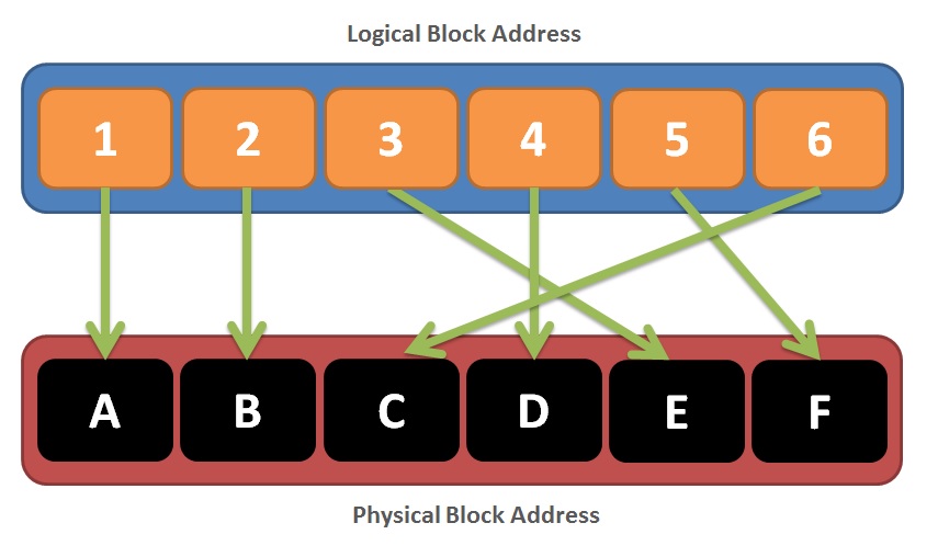
The diagram illustrates how logical block addresses (LBAs) are translated to physical block addresses (PBAs) using the FTL.
NVMe SSDs
NVMe (Non-Volatile Memory Express) SSDs are designed to fully utilize the speed of flash memory. NVMe provides several advantages:
High Throughput Interface:
- NVMe interfaces allow for high-speed access to the flash drive, significantly increasing throughput compared to older storage interfaces like SATA.
Simplified Command Set:
- NVMe uses a simple set of I/O commands such as Read, Write, and Flush.
- The Write command is internally managed by the FTL, which involves erase and write operations.
- The Flush command ensures that all pending writes that are cached are committed to the flash storage.
Direct Controller Communication:
- NVMe enables direct communication with the controller, bypassing older interfaces like inb (input byte) and loadb. This direct path reduces latency and speeds up data transfer.
ZNS NVMe
Zoned Namespaces (ZNS) NVMe drives introduce a different approach to managing data:
Partitioning into Zones:
- The drive is partitioned into zones that vary in size. Each zone is treated as an erasure block.
Zone States:
- Zones can be in different states such as empty, closed, full, read-only, or offline.
Addressing Scheme:
- Data is addressed using a combination of zone number and page number. Unlike traditional SSDs, ZNS drives do not require garbage collection.
Writing to a Zone
Write Operation:
- Specified with a page number. The operating system needs to keep track of the page number for write operations, and there's typically one pending write request at a time.
Append Operation:
- Does not specify a page number. The drive itself determines where to place the data and returns the page number where the data was written. This approach allows for multiple pending requests, but it requires more work from the operating system to manage.
- Authors

- Name
- Apurva Shah
- Website
- apurvashah.org